Preprint. The future of additive manufacturing (demo).
Through our first demo, we demonstrate how physics-based AI models can accelerate the computation behind metal 3D printing.
Metal 3D printing makes parts nothing else can, like a bracket with internal channels or a lattice at half the weight. We keep coming back to one problem: seeing a build go right, or wrong, before the laser fires. Preprint is a small first answer that runs in the browser, at apsidion.com/preprint, and it starts with heat.
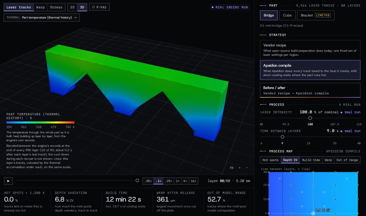
Preprint on the bridge, Apsidion compile, at 100 % power and 9 s between layers: the finished part coloured by temperature, the controls on the right, five numbers below.
The problem
In laser powder-bed fusion, a laser melts a thin layer of metal powder along thousands of short tracks, fresh powder is spread, and the cycle repeats hundreds of times. Each track is a tiny weld, and whether the part comes out right depends on how hot the metal already is under every one of them. Heat that cannot escape, in a thin wall, an overhang or a narrow bridge, piles up layer after layer. Today that is mostly found out by printing.
The three scales of a metal print. Today each is modelled in its own silo; Apsidion connects them into one model, each scale passing what it knows to the next.
- Builds are slow and costly. A plate can run for many hours, and a failed one wastes all of them.
- The settings are fixed. Open-source build preparation today gives each region one set of laser settings, whatever the heat under the track. It cannot adapt when a feature traps heat.
- The physics sits in silos. A metal print happens at three scales: the micro scale, where the metal solidifies and dendrites form; the meso scale of the melt pool; and the macro scale of the whole part, its heat, stress and warp. Today each scale is modelled on its own, in tools that are not fully connected, and too slowly to use while the settings are chosen. Yet they are one problem: the part sets how hot the metal is under each track, the melt pool sets how it solidifies, and each track sends heat back into the part (Fig. 2).
What Preprint shows
One page, three small demo parts in the nickel alloy IN718: a bridge, a cube and an overhang bracket. Two scenario axes set each view of a demo part: laser intensity (0.85× to 1.15× nominal power) and the pause between layers (6 to 40 s), alongside the strategy options. Moving the sliders shows how temperature, melt depth and distortion change across the part.
| Strategy | What it does |
|---|---|
| Vendor recipe | What open-source build preparation does today: one fixed set of laser settings per region |
| Apsidion compile | What we do: every track tuned to the heat it meets, with short cooling waits where the part runs hot (the bracket's compile has no waits) |
The part's temperature is the heart of it. The view opens on the whole part coloured by temperature, from the engine's own records of the heat in the part at the end of every fifth layer. On play, the part is built on screen: the laser beam walks each layer, its brightness the laser power on that track, the current layer's tracks are drawn on the cut, and the colour of the whole part moves with the build, blended between the engine's records (Fig. 3). Where heat collects, and how long it stays, is plain to see. The cool-down during each recoat is not drawn, and the page says so.
The bridge built from layer 1 to 80, coloured by part temperature: heat builds up in the arches and eases near the top. Real engine runs at 100 % power and 9 s between layers.
Before / after on the bridge, layers 41 to 56: the vendor recipe (left) runs hotter in the arches than the Apsidion compile (right).
The rest of the page supports that story (Fig. 4). A dropdown, thermal fields first, recolours the part by the heat accumulated under each track, the heat from tracks just scanned nearby, the peak preheat, the melt pool, the laser settings, or where the melt-pool model is outside its training data. X-ray shows every track, layer on layer; 2D shows one layer from above, with a track's numbers on hover. The replay runs from a twentieth of machine time to sixteen times faster. Warp shows the part springing (exaggerated) once cut from the plate; Stress shows stress and plastic strain on the plate.
Under the part sit five numbers: tracks landing on metal hotter than 1,300 K, how much the melt depth wanders, build time, warp, and the share of tracks outside our melt-pool model's training range. The last one is there on purpose, to show where the model is stretched. The process map beside them covers every intensity and layer time; its dots are real runs. The warp number is the true, unscaled movement: at the default point, 361 µm at most on the 12 mm bridge and 55 µm on the 5 mm cube. In the Warp view the shape is drawn exaggerated so that micrometres are visible: by default ×5 on the bridge, ×10 on the cube and ×2 on the bracket, with a slider to change it. Fig. 5 shows the three parts in three of the views.
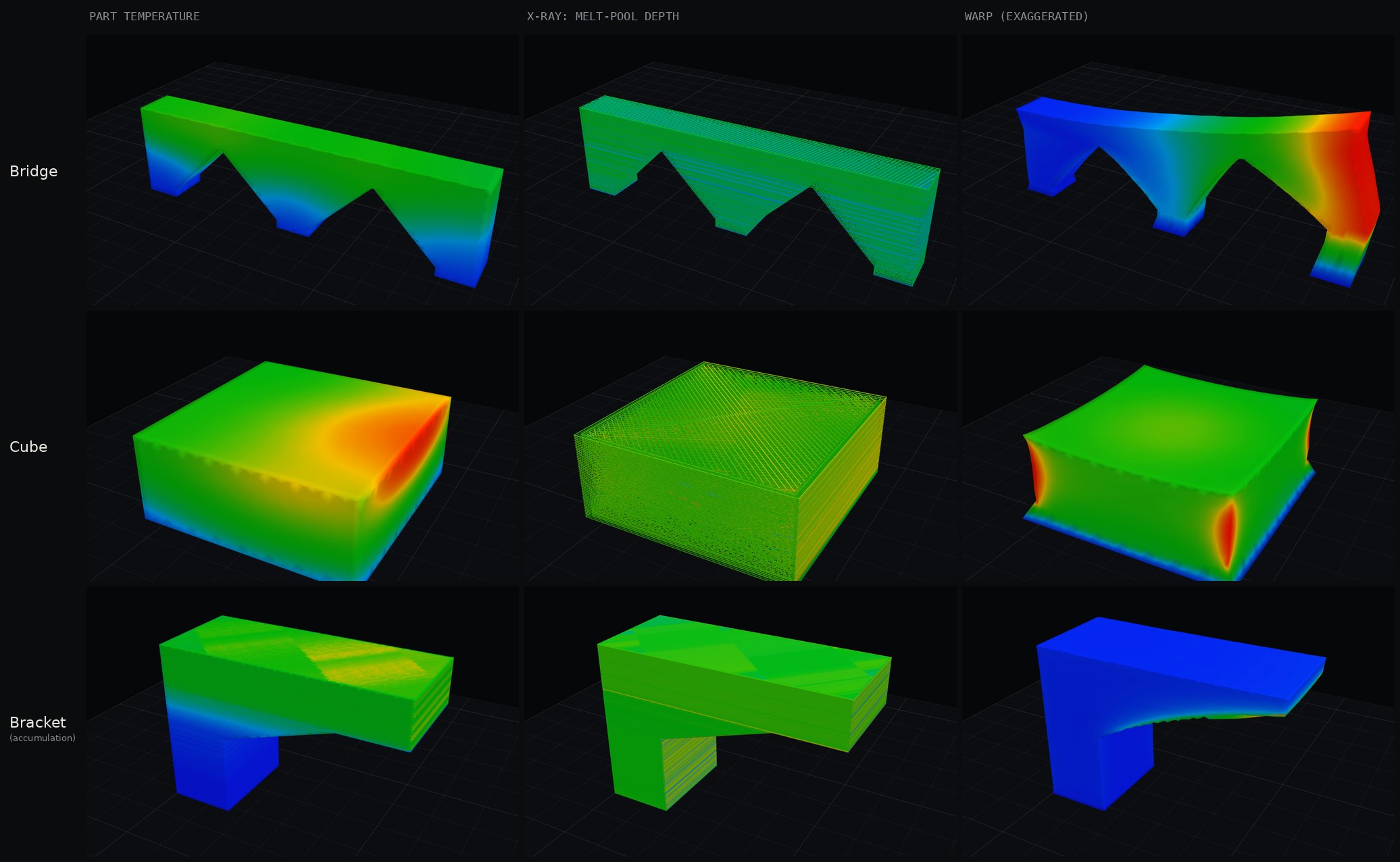
Rows: bridge, cube, bracket. Columns: part temperature (on the bracket, the heat accumulated under each track), melt-pool depth in X-ray, and warp, drawn exaggerated ×5 on the bridge, ×10 on the cube and ×2 on the bracket (the true movement is the warp number under the part).
How it was built
Three pieces of physics, coupled:
- A thermal engine that marches the whole scan path in order, on two clocks: a fast one for the heat each fresh track leaves around it, and a slow one for the whole part, which is the part temperature on screen.
- A neural melt-pool model in the loop, which predicts each track's pool from the heat already there and decides how much heat goes back in.
- Voxel finite-element mechanics on that thermal history: stress and plastic strain on the plate, and warp once the part is released.
We ran this for real on a grid: 25 runs per strategy for the bridge and the cube, plus 8 held back as a test. The bracket is the limited one: 3 runs per strategy, at one layer time. Nothing is computed while the page is open; it replays finished runs. That is a choice for the web page, not a limit of the engine: precomputing lets anyone play with the tool in a browser, because one full run of the current pipeline takes far longer than a page visit. Active work is bringing a full run down to a few minutes.
NoteDemo adaptation: how the page fills the gaps between runs
This part describes the web page, not the engine. To make a playground that runs in any browser, the finished runs are shipped compressed and blended.
Compressed. Each per-track field is stored to 8 bits, one part in 255 of its range; the part temperature is kept at the end of every fifth layer; the mechanics are sampled onto the display mesh. The three parts ship as about 19 MB in all.
Blended. Between runs, the browser blends the four nearest (Fig. 6). That is interpolation, not a new run, and the page says so every time. We measured it against the held-back runs: for the compile on the bridge, 95 % of tracks have their preheat within 14.6 K and their melt depth within 2.4 %. Some fields were never measured that way, and the page says "error not measured" for them. Where the error was too large, as on the bracket's compile, the page does not blend at all and stays on real runs.
Real runs on a 5 × 5 grid of laser intensity and layer time, and 8 held-out runs at cell centres (squares). Between runs the browser blends the four corners of the cell; the error of that blend is measured on the held-out runs.
None of the numbers are calibrated against measurements (NIST AM-Bench), and these are fixed demo parts, not yours.
Checked against incumbent tools
On a 10 mm cube we ran the same engine and mechanics next to two commercial process-modelling tools, at their laser setting. Our distortion and stress patterns match each incumbent about as closely as the two incumbents match each other, and 13 of 15 size checks land inside the range the incumbents span.
| 10 mm cube, pattern correlation (r) | Ours vs incumbent 1 | Ours vs incumbent 2 | Incumbent 1 vs 2 |
|---|---|---|---|
| Distortion on the plate | 0.96 | 0.97 | 0.95 |
| Distortion after release | 0.97 | 0.97 | 0.96 |
| Stress on the plate | 0.96 | 0.92 | 0.92 |
On top of that, we resolve what they do not: the temperature every single track meets, its melt pool, and a compiled recipe with its own power and speed per track. Neither incumbent can run per-track power and speed. Our distortion sizes sit at the high end of their range, and our vertical shrinkage after release is 2–3 times theirs, still under investigation. There is no measured cube yet: this is agreement, not proof.
One process point, worked through
The demo is at apsidion.com/preprint. It opens on the bridge with the Apsidion compile at 100 % power and 9 s between layers; with play pressed and Before / after on, the recipe and the compile build side by side.
Heat in the part: at the end of layer 55 the hottest spot of the recipe's bridge is 854 K; the compile's is 767 K, and its arches stay cooler all the way up. The numbers under the part at this default point, with the change in brackets:
| 100 % power, 9 s between layers | Bridge, recipe → compile | Cube, recipe → compile |
|---|---|---|
| Hot spots (tracks on metal above 1,300 K) | 69.5 → 0.0 % (−69.5 points) | 85.7 → 0.0 % (−85.7 points) |
| Melt-depth variation (CV) | 20.7 → 6.8 % (−13.9 points) | 11.8 → 3.0 % (−8.9 points) |
| Out of the model's range | 88.7 → 52.7 % (−36.1 points) | 90.5 → 0.5 % (−90.0 points) |
| Build time | 12 min 06 s → 12 min 22 s (+15 s, +2.1 %) | 7 min 39 s → 7 min 51 s (+12 s, +2.6 %) |
| Warp after release | 357 → 361 µm (+1.3 %, inside the noise) | 55.7 → 55.2 µm (−0.9 %, inside the noise) |
| Laser energy (power × time on track, all tracks) | 2.91 → 2.75 kJ (−5.4 %) | 3.63 → 3.87 kJ (+6.5 %) |
The cube in before / after at layer 30, then the layer slider down to layer 6 and back up to the finished part.
The cost is build time: the cooling waits add 19.7 s on the bridge, and the compiled tracks give a few back. Warp is about the same, inside the mechanics' own noise of 5.2 %, so we claim no warp benefit. And half the bridge is still outside the model's comfort zone after the compile, which is worth knowing. The cube tells the same story (Fig. 7).
The biggest change is at the overhangs. On the underside of the bridge's arches, the downskin, the vendor recipe drops to a gentle parameter set of about 110 W, and its melt pool there is a quarter as deep as in the bulk: 33 µm at the median against 134 µm, with a spread of 44 %. The contour tracks along the same edges swing the other way, up to 338 µm deep. Too shallow leaves layers unfused; too deep risks keyhole pores. The compile melts the downskin to 127 µm, the contours to 135 µm and the bulk to 128 µm, and keeps the preheat under every downskin track below 1,180 K, where the recipe's reaches 2,690 K (Fig. 8). The overhangs melt like the bulk, which gives greater confidence of a print with fewer defects in the overhangs and the other high-risk regions that usually fail first. These are the engine's numbers, not yet measured on printed parts.
Melt-pool depth on the bridge, vendor recipe (left) and Apsidion compile (right), at 100 % power and 9 s between layers. The recipe's arch edges run deep and its undersides shallow; the compile melts the overhangs like the bulk.
Moving the layer time from 9 s to 40 s is the old way of fighting heat: waiting longer between layers. The build goes from 12 minutes to 53, yet the recipe's hot spots barely move (69.5 % to 68.7 %), which suggests the harmful heat builds up within each layer. The compile spends its 20 seconds of waiting where the heat is. That trade, heat against time, is the one a compiler should make, part by part.
What comes next
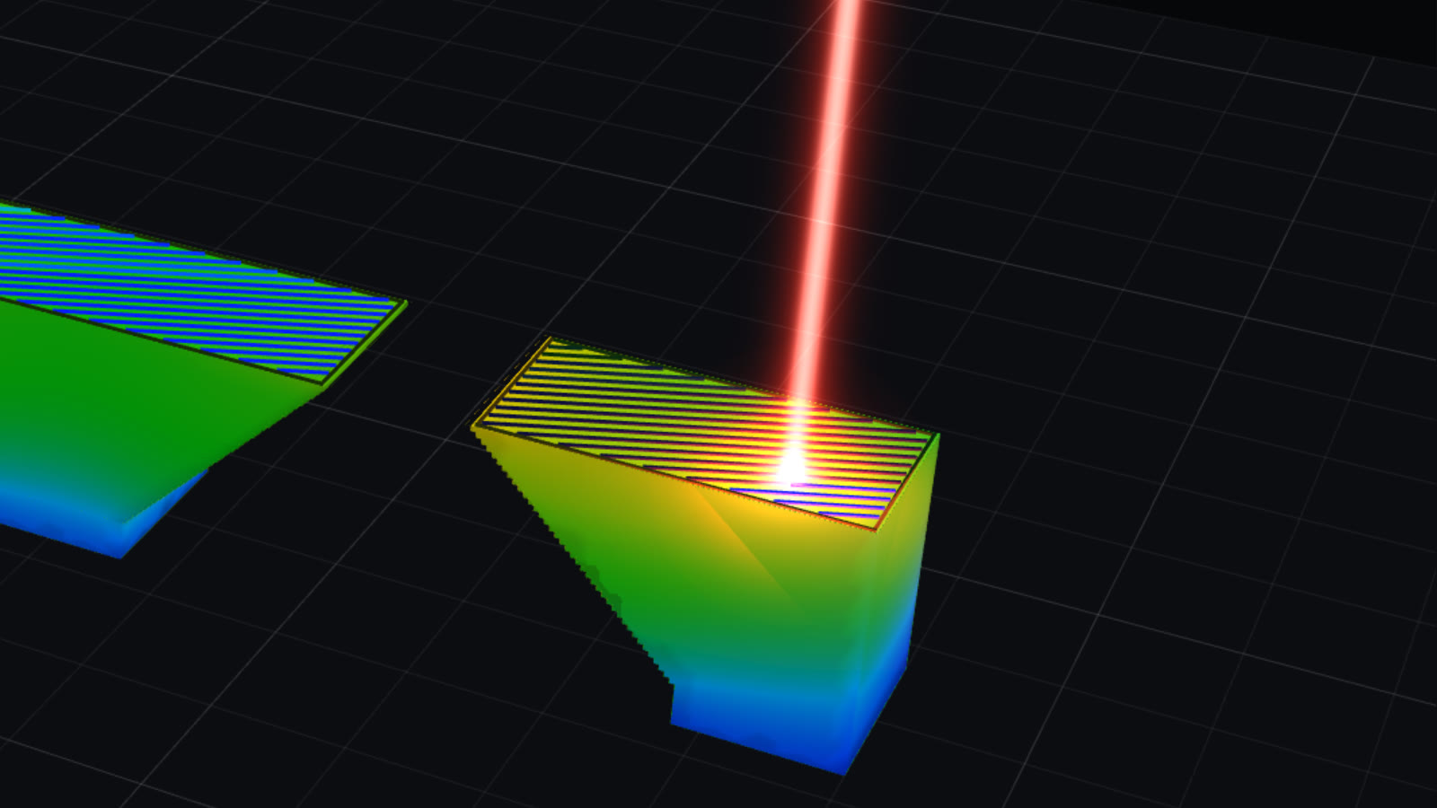
The beam on the bridge's right-hand pier at layer 47. The cut face runs hot above cooler walls.
Today Preprint is a small demo. Next, it goes to the people who print. We are bringing the engine behind it to engineers and print shops, so that everyone has access to frontier computational tools for additive manufacturing that go orders of magnitude beyond what current tools can do. Given a part, it will say whether the part can be printed, with its uncertainty, and where it will fail if it cannot.
That answer comes from inverse optimisation. The model starts from the part and works back to the process, through the machine parameters, the thermal history and the rest of the physics of the build. It tunes the whole build for that part, track by track: support structures, laser power, speed and scan path, the overhangs and the other regions that fail first, with fewer defects as the target. A part is printable when such a process exists. Designs written off today as unprintable, too thin, too steep or too quick to trap heat, become printable, because the process is fitted to the design instead of the design being cut back to fit the process. That is how design gets pushed further.
Apsidion is a small team building a physics-grounded world model, the physics playground for physical AI. Our mission is to democratize the physical world. Manufacturing is where we start, because a metal printer is where physics, cost and time meet on every single track. Preprint is a preprint in the old sense too: early work, shared before it is finished, so people can push on it.
A tiny manifesto
- We show the physics, not a promise.
- We say what is measured, what is blended and what is unknown.
- We make the slow thing instant, then make it live.
- We let the machine tune the process, so people can design what they want.